Air and Water Resistance
Author(s):
Summary:
‘F.5.3.2.2 Discovers the effect of friction force on motion in various environments. ‘The aim of this lesson plan is to experience the effect of resistance shown in air and water environments on movement is different’. In these stages of experience, robotic coding and STEM, an interdisciplinary contemporary application, were used. STEM steps used are handled in the upper interdisciplinary form. In other words, science literacy, engineering literacy and mathematics literacy are included in the event and connected with coding.
| Subject | Green Engineering and Robotics |
| Topic | Air and water resistance |
| Age of students | Secondary 10-11 |
| Preparation time | 15 Minutes |
| Teaching time | 2*40 Minutes |
| Online teaching material (links for online material) | |
| Offline teaching material |
Aim of the lesson
By the end of this lesson students will:
· realize that air and water resistance is different.
· discover by experimenting that the effect of friction force in different environments is different.
· use scientific knowledge and process to understand the natural world, as well as participating in the discussions concerning the natural world.
Activities
Describe here in detail all the activities during the lesson and the time they require. Remember, that your lesson plan needs to revolve around the topic of green engineering and robotics.
| Name of activity | Procedure | Time |
| Engage-1 | Video 1: https://www.youtube.com/watch?v=3Iz7ZMALaCY Video 2: https://www.youtube.com/watch?v=N-ZO2ILecoE | 5 min |
| Explore-1 | After the videos shown and watched, the teacher asked his students, “Have you ever thought why this mathematics or science rule in nature is like this and how?” and waits for them to say their opinions. | 5 min |
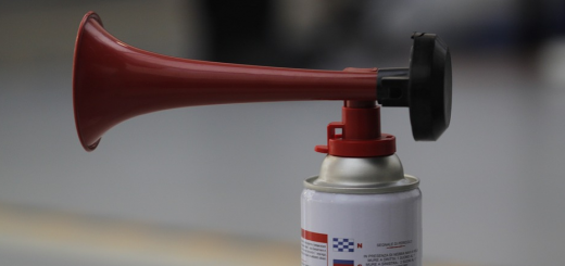
| Explain-1 | Effect of Environment on the Motion of Objects Material List to be Used: 1. Arduino Robotic Coding Board2. 1 Pieces SG90 9G Servo Motor3. 1 Push Button4. 2 Pieces Copper Plate5. 2 Pieces of Iron Balls6. Soldering Iron Machine7. Solder Wire8. Silicone Gun and Silicone9. 1 Piece of Wooden Rod10. Jumper Cable11. Ringtone12. 1 Piece 10k Resistor13. Mblock IDE Program   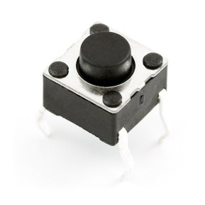 Arduino Uno 2. SG90 9G Servo Motor 3. Push button 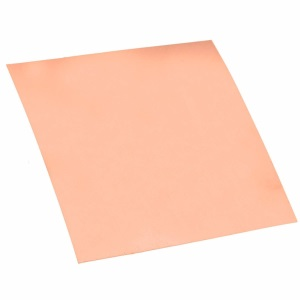 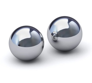 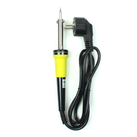 4. copper plate 5. Iron Balls 6. Soldering Iron Machine  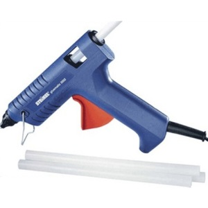 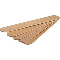 7. Solder Wire 8. Silicone Gun and Silicone 9. Wooden Rod 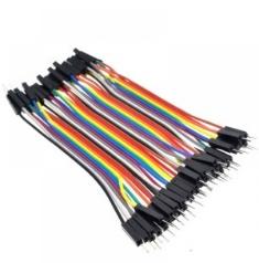 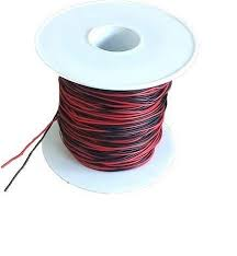 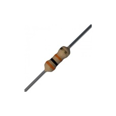 10. Connection cables 11. Ringtone 12. 10k Resitor  13. Mblock IDE The Data Obtained:With the above materials, two experimental setups will be installed where one environment is filled with air and the other is filled with water. In different friction environments, the duration meter code of the Arduino Uno board will be used to measure the time that the iron balls reach the copper plate on the ground. The data to be collected as a result of the experiment will be time. Expectation:The movement of objects will be slower as the friction resistance increases. Friction coefficient of the air-filled environment is lower than the friction coefficient of water filled environment. two iron balls left at the same height levels are expected to reach the floor later in the environment filled with water. The ball reaching the ground will contact the copper plate on the ground and complete the electrical circuit. Thus, time will be measured with Arduino. | 5 min |
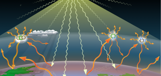
| Elaborate-1 | After the activity, which is done by using robotic coding and STEM- steps, the necessary information is transferred to the students by the teacher by using expository teaching method. Air and Fluid Resistance The friction force that occurs between the air and the object moving in the air and makes the movement of the objects difficult is called air resistance or air friction. The friction force that occurs between the fluid and the object moving in the fluid, which makes it difficult to move, is called fluid resistance or fluid friction. (This coercive or preventive force that occurs against the movement of objects moving in water is called water resistance). Air resistance affects all objects that air touches. For this reason weather resistance; affects planes, flying balloons, cars, people walking or running, cyclists, kites, falling rain, snow or hail, sky stones, stone thrown into the air, object dropped from a certain height to the ground. Fluid resistance affects all objects that the fluid contacts. For this reason, fluid resistance; affects swimmers, ships, boats, fish, submarines, and the substance that is left in the liquid. Air resistance effecting objects in the air is smaller than fluid resistance effecting objects in the liquid. Measuring the Effect of Friction Force of environment on the Motion of Objects Goal:When we leave two objects in different environments to fall free, this experiment environment was designed to examine the friction force effecting this object for each environment. Design of Experiment Setup: Two experimental environments will be prepared for this experiment. 1. Environment: A copper plate will be placed to completely cover the bottom of a transparent and deep plastic container. While one end of the approximately 1 meter long cable is soldered to the copper plate, the other end will be connected to one of the digital input pins of Arduino. This test environment will be an air friction test environment for us. 2. Environment: A copper plate will be placed to completely cover the bottom of a transparent and deep plastic container. This plastic container will be filled with water to the top point. While one end of the approximately 1 meter long cable is soldered to the copper plate, the other end will be connected to one of the digital input pins of Arduino. This test environment will be water friction test environment for us. An iron ball and a cable about 1 meter will be handled and one end of this 1meter cable will be soldered to the iron ball, the other end will be connected to the Vcc (+ 5V) pin of Arduino.A cardboard platform will be built on transparent containers, the iron ball we solder above will also be placed on this cardboard. servo motor assembly will be installed that holds the obstacle that prevents the ball from falling down. The Editing of the Experiment:In the setup, the servo motor will be rotated 90 degrees with the help of a button to remove the obstacle in front of the ball.The ball with obstacles in front of it will make a free fall from a certain height, when the obstacle is removed. At the same time, pressing the button will start the counting process on the Arduino Robotic card. *1. The ball, which is connected to the + 5V pin of the Arduino Robotic Coding card in the experimental environment, will fall to the bottom of the container due to gravity in the air environment. * The frictional force of the air while falling to the ground due to gravity will play a role in reducing the ball’s falling speed.* When the iron ball reaches the bottom, it will contact the copper plate connected to the GND pin of the Arduino Robotic Coding board. * The current coming from the + 5V end of the Arduino will pass over 1k resistor and then reaches the ball to the plate, and from the plate to the GND pin of the Arduino and the electrical circuit will be completed. * The condition will not occur when the ball is not in contact with the plate, and the condition will occur when the ball is in contact with the plate. * realization of condition means completion of free fall; time will be printed here by coding. * Thus, it will be determined how long the ball takes the specific path in the air environment, hence the average speed will be also determined. *2. The ball, which is connected to the + 5V pin of the Arduino Robotic Coding card for the experimental environment, will fall to the bottom of the container due to gravity in the water environment. * The frictional force of the water while falling to the ground due to gravity will play a role in reducing the ball’s falling speed.* When the iron ball reaches the bottom, it will contact the copper plate connected to the GND pin of the Arduino Robotic Coding board. * The current coming from the + 5V end of the Arduino will pass over 1k resistor and reaches the ball to the plate, and from the plate to the GND pin of the Arduino and the electrical circuit will be completed. * * The condition will not occur when the ball is not in contact with the plate, and the condition will occur when the ball is in contact with the plate. * Realization of condition means completion of free fall; time will be printed here by coding. * Thus, it will be determined how long the ball takes the specific path in the air environment, hence the average speed will be also determined. Our aim in the design of this experiment; is that the friction force affecting the falling object due to the environment material will be different and the movement of the falling object will be affected. Our expectation here is that the ball moving in the water will fall later than the ball moving in the air, since the friction force of the water will be more.  In the experimental environments shown above, we see the forces exerted on the iron ball. If we formulate these:Net force pulling iron ball down in Air Environment Net Force = Gravity Force – Friction Force of Air In the experimental environments shown above, we see the forces exerted on the iron ball. If we formulate these:Net force pulling iron ball down in Air Environment Net Force = Gravity Force – Friction Force of AirThe net force that pulls the iron ball down in the Aquatic Environment will be as follows Net Force = Gravity Force – Friction Force of Water – Lifting Force of Water Iron ball will accelerate at the rate of net forces applied and will decrease rapidly proportional to the net force applied to iron ball. Lifting Force of Water will be ignored in our experiment here. Water Friction Force is known to be more than Air Friction Force. Therefore, the force applied to the object in the air environment is higher than the force applied to the object in the water environment. As a result, the identical object in the air will fall faster than the identical object in the water. Description of Ball’s Direction of Movement:When the experimental environment was first set up, it was decided that the direction of movement of the ball should be made by pulling up and down by DC motors and the experimental setup below was designed. 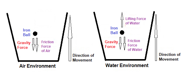 In these experimental setups, the net forces acting downward on the iron ball while the object is being pulled upwards: In these experimental setups, the net forces acting downward on the iron ball while the object is being pulled upwards:In Air Environment Net Force = Gravity Force + Friction Force of Air In Water Environment: Net Force = Gravity Force + Friction Force of Water – Lifting Force of Water In this experimental environment, the lifting force of the water creates a lightening effect on the object in the water and has a negative effect on our experiment environment. With the pulling force applied to the object in the water due to the lifting force of the water, the object can come out faster, this is a situation we don’t want. Therefore, it was decided to apply the experimental environment in which the iron ball was left down. Necessary materials: 1x Arduino Uno Robotic Coding Board1 x Breadboard1 x SG90 Servo Motor1 x Push Button2 x Copper Sheet1 x Iron Balls3 x 1 meter copper cable1 x 10k resistor Introduction of Servo Motor and Pin Connections:Servo motors are the systems that enable the gears on them to turn up to 180 degrees by means of the mechanism inside them. There are 3 pin outputs, these are Vcc, GND and PWM. The gear of the servo motor is at the position given by the PWM pin. Thus, we can direct the servo motor by giving the desired angle value from Arduino. To define the functions of pin outputs: 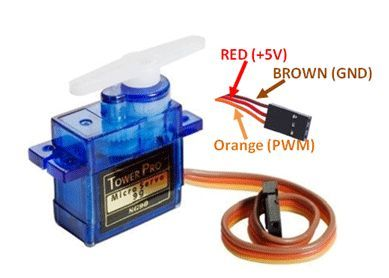 Vcc: Required for the operation of the devicepin to which the voltage is given GND: pin required for the completing the electrical circuit PWM: The pin gives the angle value for Servo motors to takes position.  Introduction of Buttons and Pin Connections:Buttons are used to open or close a circuit in electrical and electronic systems. They are connected in series to a system. Energy flow is provided by pressing the button, so energy goes into the system and the system starts working. The electrical circuit cannot be completed when the button is not pressed, so no energy flow can be provided, so it doesn’t work because there isn’t energy to the system. The purpose of use here is to transmit the energy connected to one pin to the other pin when pressed. It will not be able to transmit when it is not pressed. Making Copper Plate and Ball Connections:For water environment For Air Environment 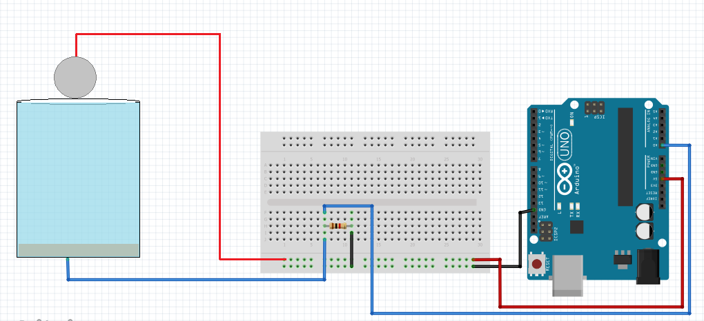 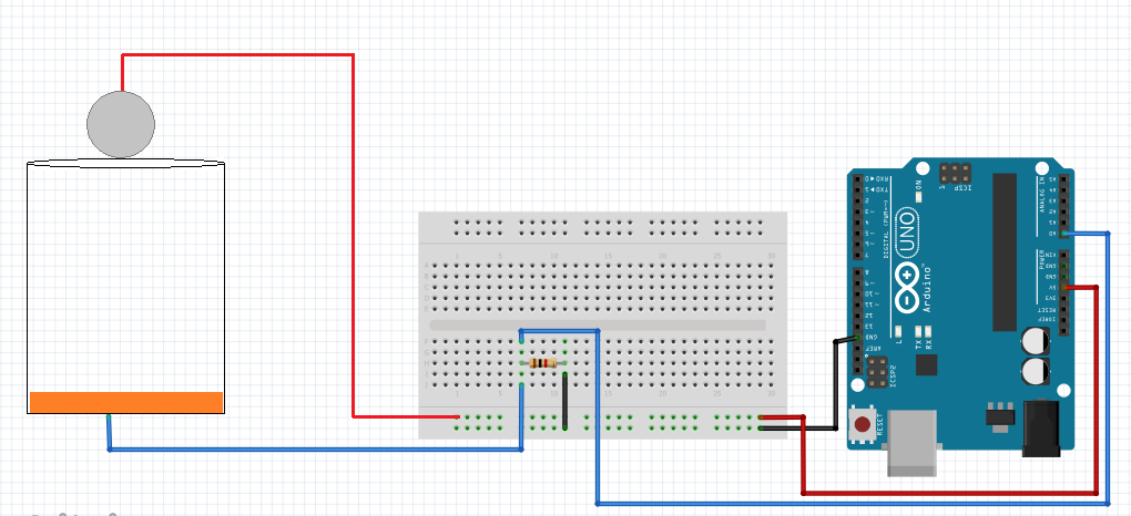 As seen in the above figure, copper plate and iron ball act as a resistor. When the iron ball is not in contact with water, there is infinite resistance between the copper plate and when the iron ball is in contact with the water, water resistance occurs with the copper plate, and when the iron ball contacts the copper plate, the resistance becomes 0. The voltage divider logic was applied by adding a 1k resistor after the copper plate, and the voltage on the 1k resistor is measured from the A0 Analog pin of Arduino.When the iron ball is not in contact with the water, the value read on the A0 Analog pin will be 0. When the iron ball is in contact with water, the value read from the A0 Analog pin will change depending on the water resistance, but will still be less than 1000. When the iron ball touches the copper plate, the value read on the A0 Analog pin will be greater than 1000. Thus, it can be determined whether the iron ball has fallen to the ground. Making Circuit Connections: 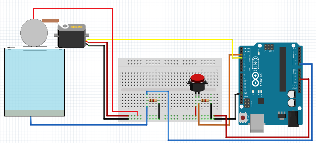 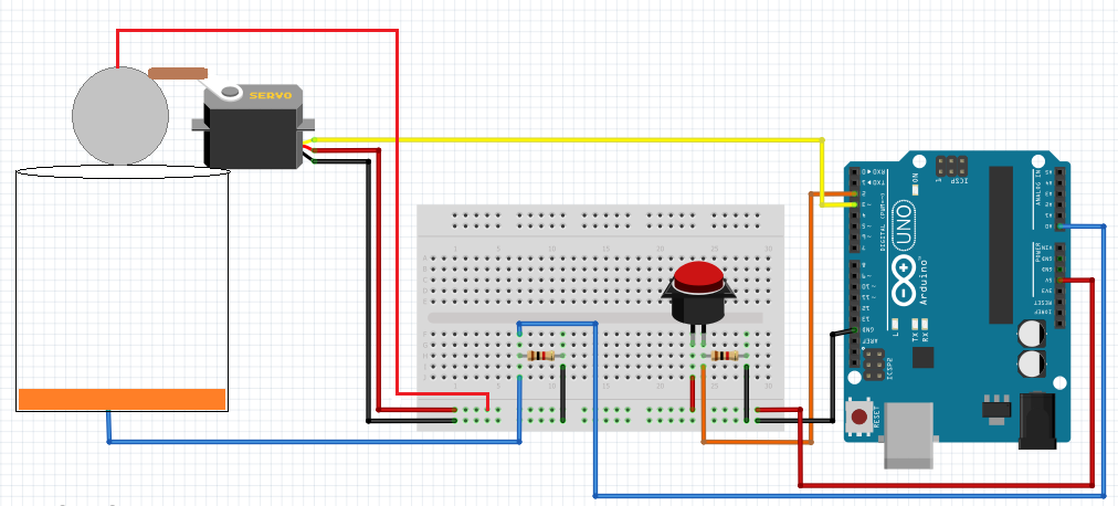 Firstly, as mentioned above, two environment set-ups which contain transparent and deep plastic containers, will be prepared. A copper plate will be placed to completely cover the bottom of both of these containers. The containers will be filled with tap water, the second one won’t be filled. One end of the 1 meter cable will be soldered to the copper plate we placed at the bottom of the first environment container. The other end of the cable will be connected to Arduino’s digital pin 5. One end of the 1 meter cable will be soldered to the copper plate we placed at the bottom of the second experiment container. The other end of the cable will be connected to Arduino’s digital pin 4. One end of 1 meter cable will be soldered to the ball resting on the experiment container, the other end will be connected to the Vcc (+ 5V) pin of Arduino. The connections of the servo motor, which will let the ball fall free, will be made as follows: Servo Pins Arduino Pins Vcc Vcc (To activate the device) GND GND (To complete the power circuit) PWM D3 (To give the turning angles) A button will be used to operate this circuit. Servo will turn 90 degrees when this button is pressed, remove the obstacle in front of the iron ball and will make the iron ball fall. Also, pressing the button will start counting from 0. One end of the button will be connected to the Vcc pin and the other end to the digital pin 2 of Arduino. Here, a pull-down resistor of 1 kohm is used to prevent instability. One end of the pull-down resistor will be connected to the end of the button that goes to Arduino and the other end to the GND pin of Arduino. The application we will use for coding is the Mblock program. This application is a tool that allows us to do robotic coding by dragging and dropping blocks without the need for programming language knowledge. Coding block is below. 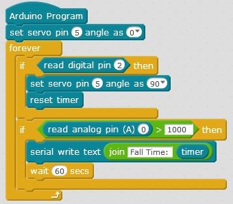 If we explain the application steps one by one: Set Servo Pin ( ) Angle As ( ) block: This code block enables to rotate the servo motor connected to the specified digital pin of the Ardunio at specified angle. In our project, Servo motor is connected to pin 5 of Arduino and 0 and 90 degrees will be rotated. Digital Pin Reading () block: Indicates that data from the given Digital pin of Arduino () in parentheses are read. Data from digital pins can only be 0 or 1. In this project, data from digital pin 2 is read. If () then block: If the expression that comes in parentheses with this block of code is logically “True”, all blocks placed in the block work. If it is logically “False”, this and the code blocks in it are passed without running. 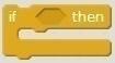 Timer Reset block: It is stated that with this code block, a time counter starting from 0 is started in Arduino. Read Analog pin (A0) block: It is stated that the data coming from A0 Analog pin of Arduino has been read. Data here is the voltage received. ( ) ile ( ) comparison block: This block compares two values in parentheses. If they are same, it results “True” or 1, they are not, it turns “False”or 0. It is questioned that whether the value read from Arduino’s A0 Analog Pin is greater than 1000. Timer block:It keeps the time after resetting time block. The unit is seconds. ( ) ile ( ) combine block: This block combines two values in parentheses. Here it will be combined “Fall Time” and time from the timer. Serial Write Text ( ) block: This block allows to be sent the variable that comes in parentheses to the the serial port so the computer via USB cable. ( ) ile ( ) combine and Serial Write Text block:It combines what is written in parentheses and sends this value to the Serial port, that is, to the computer. Here, in parenthesis, it will combine the value of “Fall Time:” with the timer and write it to the Serial port, that is, send it to the computer. Wait ( ) secs block: Arduino Robotic Coding board will wait without doing anything for the given seconds when it sees this block .In our experiment here, 60 seconds were entered to give time to be able to read the time displayed on the screen. Forever block: As long as Arduino is open, it provides continuous repetition of the blocks placed in it. This process will be done continuously unless Arduino is closed. 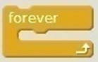 The block when Arduino Uno starts: This block represents energizing the Arduino Robotic Coding device. It means that code blocks added as a chain will be executed when energized and started to run. ● As a chain to the block “When Arduino Uno starts” the block “Set the angle of 5 servo pins to 0” comes. With this code block, the angle of the servo that pushes the ball is adjusted.● Then the condition in “if () block” will be queried. The requirement here is that the value of “(2) Read Digital Pin” is 1. This means pressing the button connected to Arduino’s digital pin 2.● After pressing the button connected to pin 2, the code block chains under it starts working. The first code block is “Make 5 servo pin angle 90”. This block of code will rotate the servo connected to pin 5 by 90 degrees. This ensures that the obstacle in front of the iron ball is removed in the experimental environment and the iron ball is in free fall.● The next code chain is “Reset Timer”. This block of code also enables a timer in Arduino to be activated and the timer is started from 0 as of this code. Thus, when the iron ball starts to fall, the counter is started.● Now we need to run our program until the iron ball contacts the copper plate under the container. We use a new “if ()” block because we don’t know how long it will take. The requirement of this block is that the value read from the A0 Analog pin is greater than 1000. Because the resistance of water and the 1k resistance used in series are used as a voltage divider and measurements are taken between these two resistors. Arduino’s iron ball connected to the 5V pin falls to the ground, which means it comes into contact with the copper plate, meaning that the water resistance is 0. Therefore, it means that the value we read from Arduino’s A0 Analogue pin is greater than 1000. Thus, it can be determined whether the iron ball has fallen to the ground.● When the iron balls are combined with the copper plate, the value of the timer will be combined with the text “Fall Time:” and printed on the serial port. Then, 60 seconds delay is given so that this printed time does not disappear from the screen immediately, it is expected to be read and recorded in 60 seconds.The fall time of the balls will be printed on our screen in both air and water environments. The distance that the balls travel on the vertical axis is determined in the experimental environment.With a simple calculation, Speed (V) = Path (X) / Time (t) and average speed are found. | 25+25 min |
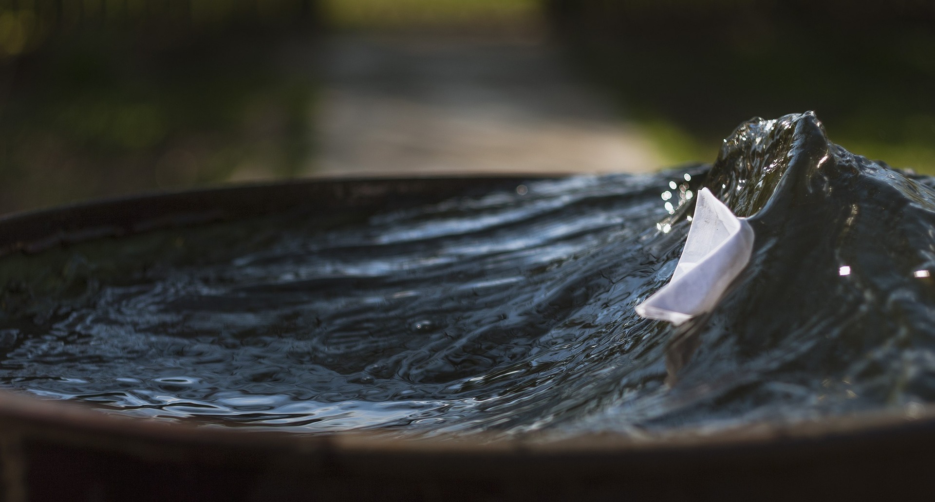
| 5. Evaluation | Materials Used:Mandatory materials: pet bottle, ice cream stick, button, toothpick, glue, crayons (6 colors), scissorsMaterials that are not mandatory to use: You can use 5 different materials you want.Knowledge Based Life ProblemKingfisher Birds According to a rumor, it is believed that people named like this because they spied the Istanbul mansions outside the windows. The English name is known as “king fisher”. The most well-known features of this bird are that it dives into the water very quickly and catches its prey in a few seconds with its beak.The kingfisher bird must calculate very well the angle of refraction and ingress of water before catching its prey. If this is not calculated, it may miss its prey or even its neck may be broken due to the surface tension or density of the water or permanent injuries may occur. It has been determined that these birds, which can dive into the water from the sky very quickly, increase the speed thanks to the pointed structure of their beaks.When the kingfisher feeds its cubs, it puts its prey upside down in its crop, so that when it returns to the nest, it can swallow the fish straight without difficulty, it is a good example of the affection and compassion that creatures show to their cubs. It was thought to feed the cub without difficulty; the prey was hidden in the crop. Unaware of this situation, the cub easily swallows the pre-caught food. GoodMediumShouldBe improved Mandatory materials used? Have the limitations been complied with? Is the problem scenario understood? Is the brochure sufficient to promote the product? Can the model move? What is the reason that kingfisher birds can be so fast? What is your thoughts about it?Can you design a vehicle (air, land, water) based on the characteristics of kingfisher birds?Limitations:Budget is limited to 20 Euro.The length of your model should be minimum 30 cm and maximum 45 cm.Your model must have a name.Your product must have a promotional brochure. Evaluation of the Product Created: | 15 min |
| X min |
Assessment
Describe here the assessment method of the lesson, if any. For example, if you plan on assessing your students with a quiz, include here questions and answer options with color-coding the correct answers.